

My New App! Hello reader, while you’re here I would appreciate it if you could check out my new app Sync Timer on Google Play. It’s a timer app which synchronises between all of your Android devices (and it uses AnimatedVectorDrawables too!)
In Android version 5.0, Lollipop, Google introduced its own vector graphics format, the VectorDrawable. The benefits of using vector graphics are numerous when dealing with a wide range of screen sizes, but in this article I’ll be discussing another aspect, the ability to manipulate how images are drawn in real time so they can move and change on the screen. In this case I’ll be showing how we can use the AnimatedVectorDrawable class to create this effect, morphing between the Android and Apple Logos.
The full source code is available on GitHub.
I’ll start with a brief introduction to VectorDrawables in Android, using a simple example:
 <vector xmlns:android="http://schemas.android.com/apk/res/android"
     android:height="64dp"
     android:width="64dp"
     android:viewportHeight="600"
     android:viewportWidth="600" >
         <path
             android:name="v"
             android:fillColor="#000000"
             android:pathData="M300,70 l 0,-70 70,70 0,0 -70,70z" />
 </vector>
This contains a <path> element inside a <vector> element. In this article I’ll be mainly focussing on the <path> section and what we can do with it.
The first thing to know when considering animating a VectorDrawable with a changing shape is that, as stated in Google’s overview: “the paths must be compatible for morphing. In more details, the paths should have exact same length of commands, and exact same length of parameters for each command”. So what does this mean in practice?
Looking at the example above, the entry android:pathData=”M300,70 l 0,-70 70,70 0,0 -70,70z” defines the outline of the VectorDrawable. The syntax for pathData is the same as that for Scalable Vector Graphics(SVGs) and I’d recommend you have a read through and familiarise yourself with that if you plan on trying to manipulate the pathData of a VectorDrawable.
Some basic rules are:
-
pathData includes coordinates. Like in other parts of Android, the x-axis goes from left to right and the y-axis goes from top to bottom, so the point 0,0 is at the top-left of the screen.
-
Letters are used to instruct what the current type of command is and can be upper or lowercase. Uppercase commands mean the coordinates given are absolute and lowercase means they are relative to wherever your ‘pen’ is currently. So M50,50 means move the pen to coordinate 50,50 on your canvas, whereas m50,50 means move 50 to the right and 50 down from wherever your pen already is at that point in the pathData instructions.
In our example here the pathData breakdown is thus:
M300,70 : M is the moveto command and the numbers are coordinates, so this means move the ‘pen’ to position 300 on the x-axis and 70 on the y-axis, we’ll start drawing there.
l 0,-70 70,70 0,0 -70,70 : l is the lineto command, which draws straight lines, and the numbers are again coordinates. Note that this is a lowercase l therefore these coordinates are all relative.
- Starting at position 300,70 we draw a vertical line upwards(0,-70)
- from there a diagonal line 70 down and 70 right(70,70)
- then 0,0 a line of zero size(more on this in a moment)
- then a diagonal line 70 left and 70 down(-70,70).
Finally z which means closepath, it draws a straight line from where we are now, back to our starting point.
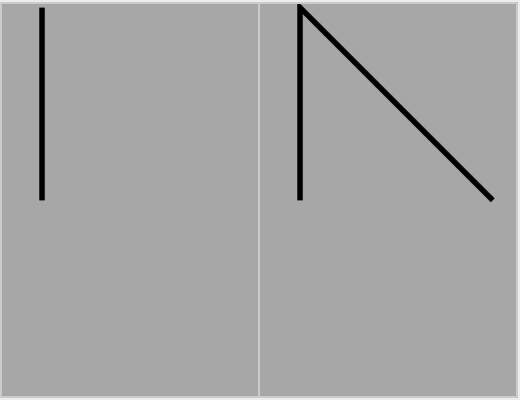
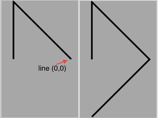
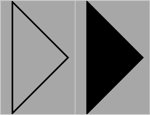
So this particular pathData draws us a right-angled triangle.
Now that we have an idea of what pathData looks like and does, we can go back to that quote from Google earlier:
“Note that the paths must be compatible for morphing. In more details, the paths should have exact same length of commands, and exact same length of parameters for each command”
What this means is that if you want to morph one set of pathData into another then a letter in one path needs to match a letter in the other path and each number in the first path needs a corresponding number in the other path. You cannot morph an L command(lineto) into a C command(curveto), you can’t even morph a C into a c, it must be the same letter and the same case. You also cannot morph a lineto command with three coordinates,maybe a triangle, into a lineto command with four coordinates like a square.
You may have realised at this point why the triangle pathData we looked at had a set of coordinates(0,0) which appeared to be completely unnecessary. If all we wanted to do was draw the triangle then it would indeed be unnecessary, however if we want to morph the triangle into a more complex shape that does require more coordinates then we need to make sure they both have the same number, and the (0,0) line does that.
In order to achieve the path morph between the Android and Apple logos, we need to do a similar thing to make sure the pathData is compatible. The two logos are clearly quite different, so it takes a bit of manipulation to make them compatible, which I’ll go through here. A more common use case for this type of pathMorphing may be to transition between simple icons like play->pause or tick->cross, but if you grasp the process here, you’ll be able to apply it in these cases.
The first thing I needed was to have the logos in the appropriate format. As mentioned earlier VectorDrawables are related to one of the most common vector graphic formats, the SVG. I pulled a couple of SVG files for the Apple logo and the Android robot and used the svg2android online conversion tool to get my starting point. I also opened the SVG files up in VectorDraw to see what I’m really dealing with. I realized pretty early on that when I’m going to start messing about with the pathData to make these compatible, that I have a far better chance when manipulating the Android logo with its straight lines and regular shapes than I would trying to change the Apple logo which is made entirely of cubic Bezier curves. I decided to leave the Apple logo as-is as much as possible and to change and re-create the Android logo as needed.
Another thing struck me when looking at the images in VectorDraw. It seemed clear that the Android head and the Apple leaf would work well as a set of objects to morph between. The apple itself would be trickier, but I noticed similarities between the Android’s arms and the apple which gave a good direction to follow.

Splitting the apple down the middle, each half matches up fairly well with an arm, with a curve at the top and bottom and a similar number of lines. I decided to proceed on this basis, morphing the head into the leaf and the arms into the apple, then find a way to blend the body and legs into the process.
The apple leaf is made up of four curveto lines as follows:
m108,35
c5.587379,-6.7633 9.348007,-16.178439 8.322067,-25.546439
c-8.053787,0.32369 -17.792625,5.36682 -23.569427,12.126399
c-5.177124,5.985922 -9.711121,15.566772 -8.48777,24.749359
c8.976891,0.69453 18.147476,-4.561718 23.73513,-11.329308
That’s a lot of numbers. c is a cubic Bezier curve, each of these has three coordinates. The curve starts wherever the pen already is at that stage in the path, and ends at the third and final coordinate. The other two coordinates define what exactly the curve does between those points, but I won’t go into too much detail on that here.
So I made an Android head equivalent:
m85,40
    c10,0 20,0 30,0
    c0,-5 -10,-20 -30,-20
    c-20,0 -30,15 -30,20
    c10,0 20,0 30,0
Two of the c commands here aren’t really curves at all of course, c10,0 20,0 30,0 defines a curve with all of its points along zero on the y-axis, so it’s really a horizontal line. Using this trick means that the Android head and the Apple leaf pathData are now compatible: each has one m command followed by four c curves, and they both have the same number of coordinates in the right places, although the leaf uses many more decimal places.
So far these are not animated though, just the starting state and finishing state. To make a transition from one to the other, we need to define the change in some xml files.
We have our android head VectorDrawable which defines our original static vector in res/drawables in the file android_logo_vector_morphable.xml:
<?xml version="1.0" encoding="utf-8"?>
<vector xmlns:android="http://schemas.android.com/apk/res/android"
   android:viewportWidth="170"
   android:viewportHeight="170"
   android:width="500dp"
   android:height="500dp">
   <path
       android:name="head"
       android:fillColor="@color/android_green"
       android:pathData="M85,40
                          c10,0 20,0 30,0
                          c0,-5 -10,-20 -30,-20
                          c-20,0 -30,15 -30,20
                          c10,0 20,0 30,0"/>
</vector>
Our objectAnimator set which defines what the change will be is in res/animator in the file head_leaf_transition.xml. Notice I’ve actually included two animators in the same set, to change the shape and the colour:
<?xml version="1.0" encoding="utf-8"?>
<set xmlns:android="http://schemas.android.com/apk/res/android">
<objectAnimator
   android:duration="@integer/morphing_time"
   android:propertyName="pathData"
   android:valueType="pathType"
   android:valueFrom="M85,40
                      c10,0 20,0 30,0
                      c0,-5 -10,-20 -30,-20
                      c-20,0 -30,15 -30,20
                      c10,0 20,0 30,0"
   android:valueTo="M108,35
    c5.587379,-6.7633 9.348007,-16.178439 8.322067,-25.546439
    c-8.053787,0.32369 -17.792625,5.36682 -23.569427,12.126399
    c-5.177124,5.985922 -9.711121,15.566772 -8.48777,24.749359
    c8.976891,0.69453 18.147476,-4.561718 23.73513,-11.329308"/>
    <objectAnimator
        android:duration="@integer/morphing_time"
        android:propertyName="fillColor"
        android:valueFrom="@color/android_green"
        android:valueTo="@color/apple_black"
        />
</set>
Tip: I’m including the full pathData in these code snippets to keep everything together. In practice you can store these as Strings in your values folder and instead refer to them using the @string/android_head style for easier reuse.
and our animated vector drawable in res/drawables which connects the two:
<?xml version="1.0" encoding="utf-8"?>
<animated-vector xmlns:android="http://schemas.android.com/apk/res/android"
   android:drawable="@drawable/android_logo_vector_morphable">
   <target
       android:animation="@animator/head_leaf_transition"
       android:name="head"/>
</animated-vector>
Note that in our original VectorDrawable the path has the name “head” and in our animated-vector, the <target> attribute targets that path name. Essentially this is an instruction to apply this animator to this path. The transition looks like this:
There are some missing elements from the head here – the eyes and the antennae. They don’t have an obvious equivalent to morph to, so we’ll just make them disappear.
<!--partial code from right antenna objectAnimator -->
<objectAnimator
...
android:valueFrom="M95,25
                  l6,-10"
android:valueTo="M95,25
                  l0,0"
.../>
This makes the eyes disappear as if they were closing and the antennae just shrink away, leaving the way clear for the head to transition cleanly into a leaf.
When adding these extra transitions, we use the original VectorDrawable and just add a new <path> tag for each shape, and the original AnimatedVectorDrawable with a new <target> tag for each shapes animation. We do however need a separate objectAnimator for each one.
Then we apply the same principles to the next part of the transition. For my method I split the apple in two and worked on one arm at a time, again the trick here was to make sure the arms were fully constructed using the same number of curveto commands as the apple, so some of these were curves which were actually straight lines, and some weren’t really lines at all, just zero-length curves (c0,0 0,0 0,0). So now we have:

At this point everything’s really falling into place; the end result is great but we need to bring in the Android body to bridge the gap in the middle. This part is a lot simpler: the body is simply stretching a bit to disguise the fact that two separate halves are joining together. The legs don’t actually need to do anything, as they’re obscured by everything else, so we’re essentially done. We can add some interpolators to our objectAnimators to make the whole thing a bit more satisfying with a bounce effect and a nice overshoot for the leaf to settle into place and voilà – the final product:
Don’t forget the full source code for this project is available on GitHub.
Note: I haven’t gone into full exhaustive detail here about this implementation, there are some frustrations I found along the way(particularly when using startOffset) which I may turn into future posts and/or bug reports.